Our Problem:
Design and build a robot that can assist a person with a disability or an elderly person in accomplishing a daily task.
Basic Requirements of Robot Design:
. The robot can either be a full size model or a scale model.
. It must use sensors to respond to its environment.
. It must exhibit complex decision making, such as reacting in different ways depending on what it senses from light and/or touch sensors.
. The program must include forks or jumps.
. The robot can either interact with a person or, operating autonomously, interact with the environment.
Our Solution:
In consideration of the basic requirements, we decided to target our design on those whose disability disallows the use of the human hand. This mechanism will have two main objectives: to grab and release whatever object it must grab.
Programming:
The programming is the essential factor of the claw's efficiency. Seeing that we are limited to one programming box/power box, as well as only two touch sensors (when we needed essentially three of them), we decided to create a prosthetic claw. This mechanism was to have two main objectives: to grab ahold of whatever object it "recognizes," and to release this said object.
On the claw there is one touch sensor that upon being "released," the claw would begin to close. By released, that means that the pressure on the touch sensor is applied, and the program shall not work till the pressure on the touch sensor is alleviated. Once the claw begins to close, and pressure is once more applied onto the first sensor, the claw stops its current function. For the claw to open, the other touch sensor must be pressed. There is a switch that is pressed manually, and this then causes the other part of the program to begin its function, releasing the object. Once the claw expands a certain distance, the claw stops its release function.
The program is set to loop, allowing the user of the "prosthetic claw" to use it a multitude of times, increasing the efficiency.
The Result:
The claw was successful. When an object touched the sensor, the claw grabbed onto it and when the object was set down onto the table, the claw released. It performed its basic functions exponentially and proved to be an efficient design. Also, the efficiency of the claw is based on the user's ability to adapt with it; thus it is expected that the user masters the claw and uses it to its fullest potential.
Thursday, March 13, 2008
Tuesday, March 11, 2008
Wallace and Grommit
Our problem:
Design and build a device that can deliver a person from a bed on the 2nd floor to the seat at the kitchen table on the 1st floor. The system should be activated by the rising sun (simulated by a flashlight).
Basic Requirements of Robot Design:
. The device used to transport the mini Wallace must not be touching it at the end of the challenge.
. The house must include a bed on the second floor.
. Mini Wallace should land in the chair, not touching the floor.
. Extra credit: have jam hit mini Wallace's face while sitting on the chair.
Our Solution:
Programming:
The mechanism that the main inventor designed needed to use not only the basic touching sensors, but also a light sensor because of the situation of this problem. Inspired by the Wallace and Gromit animation, the platform Wallace rests upon is in actuality the bed, which at the break of dawn is activated to tilt to slide him down into his chair (strangely with a pair of pants for him to slide into). Thus, a light sensor was a mandatory requirement for the design.
First the light sensor was programmed, with a power level installed into the programming. This way, it would not activate under the normal lighting of the classroom, and required a powerful level of brightness to activate (ex. flashlight). Upon its activation, the motor powering the elevator component of the mechanism would begin to descend, tilting the platform. At that moment, the first touch sensor programmed into the mechanism would be activated, and a program delay would thus begin to countdown. This then allows Wallace to slide down from the platform and into the chair. Once the time runs out, the elevator platform begins to ascend and "disappear" from the view of the room until it touches the second touch sensor. Upon tapping that touch sensor, it stops the elevator and activates the second component of the mechanism.
The second component of this mechanism is the catapult system which held the jam that would be thrown into Wallace's face. Designed on the other side of the first floor platform, its trajectory was "calculated." When the second touch sensor is pressed, the program in the catapult system is activated. Given a time delay, it propels the jam (lego block) from its arm right into Wallace. This then ends the program and ends the purpose of this mechanism's design.
The Result:
Our design successfully placed mini Wallace right into his chair. As the platform raised back up, the hook flung the jam, lego, dead onto his face. He was not a happy camper. =] .
For those in the class, we ALL KNOW who exclaimed when the elevator component went back up (cough cough STEVE). And sure enough, the poor mini Wallace did get hit in the face . . . a lot, I wouldn't be surprised if he was still smelling the stuff after cleaning off, hard to get it out of the nose. ;3 Nevertheless, this proved to be successful.
Design and build a device that can deliver a person from a bed on the 2nd floor to the seat at the kitchen table on the 1st floor. The system should be activated by the rising sun (simulated by a flashlight).
Basic Requirements of Robot Design:
. The device used to transport the mini Wallace must not be touching it at the end of the challenge.
. The house must include a bed on the second floor.
. Mini Wallace should land in the chair, not touching the floor.
. Extra credit: have jam hit mini Wallace's face while sitting on the chair.
Our Solution:
We built a device that worked like an elevator. As the platform on the second floor lowers, it placed mini Wallace directly into his chair. On the other end of the house, we designed a hook-like mechanism that is made to fling jam, a block of lego, right onto mini Wallace's face.


Programming:
The mechanism that the main inventor designed needed to use not only the basic touching sensors, but also a light sensor because of the situation of this problem. Inspired by the Wallace and Gromit animation, the platform Wallace rests upon is in actuality the bed, which at the break of dawn is activated to tilt to slide him down into his chair (strangely with a pair of pants for him to slide into). Thus, a light sensor was a mandatory requirement for the design.
First the light sensor was programmed, with a power level installed into the programming. This way, it would not activate under the normal lighting of the classroom, and required a powerful level of brightness to activate (ex. flashlight). Upon its activation, the motor powering the elevator component of the mechanism would begin to descend, tilting the platform. At that moment, the first touch sensor programmed into the mechanism would be activated, and a program delay would thus begin to countdown. This then allows Wallace to slide down from the platform and into the chair. Once the time runs out, the elevator platform begins to ascend and "disappear" from the view of the room until it touches the second touch sensor. Upon tapping that touch sensor, it stops the elevator and activates the second component of the mechanism.
The second component of this mechanism is the catapult system which held the jam that would be thrown into Wallace's face. Designed on the other side of the first floor platform, its trajectory was "calculated." When the second touch sensor is pressed, the program in the catapult system is activated. Given a time delay, it propels the jam (lego block) from its arm right into Wallace. This then ends the program and ends the purpose of this mechanism's design.
The Result:
Our design successfully placed mini Wallace right into his chair. As the platform raised back up, the hook flung the jam, lego, dead onto his face. He was not a happy camper. =] .
For those in the class, we ALL KNOW who exclaimed when the elevator component went back up (cough cough STEVE). And sure enough, the poor mini Wallace did get hit in the face . . . a lot, I wouldn't be surprised if he was still smelling the stuff after cleaning off, hard to get it out of the nose. ;3 Nevertheless, this proved to be successful.
Tuesday, March 4, 2008
Tug-O-War Robot
Problem:
Design and build a tug-o-war robot using Pilot Level 4 or Inventor Level 4 to program the robot. The objective is to pull the opposing robot over the centerline. The battle commences when both robots are activated by a single touch sensor.
Basic Requirements of Robot Design:
1) Input Port 1 must be accessible to connect the touch sensor lead wire to.
2) You may use a maximum of two motors.
3) Your robot must permit a piece of string to be attached (you decide how).
4) Your robot must fit inside a cube 9 inches on a side.
Our Solution:
We developed a robot whose build and weight would enable it to slowly pull the opposing robot. The design of the gears enabled the robot to use a great amount of torque, while the outer shell of the robot made it very difficult for it to be overpowered. Also by incorporating a pulley system in the axle of the frontal wheels, it was assumed that it would be capable of pulling the opposing robot upward and disabling two of its four wheels.
 Picture: LegoVikings' Robot (right) vs. ??? Robot (left)
The Result:
Unfortunately, the robot lost in the first round due to a fatal design error the pulley system. It would have been an advantage if it wasn't for one VERY important factor: the string that the would connect the opposing robot to our own. With the limited amount of string given, we could not use the full potential of our robot's design which was the pulley system. The string was also attached to the pulley pole, which was another fatal error. There was little to no power or weight in that part of the robot, which easily gave the opposing robot a major advantage as it used the weight of our robot against it. The result . . . had our robot literally pulled onto its back and over the line.
If it was not for the limiting string, our robot would have had at least a "fighting chance," but there can be no such assumption. However, the errors of our design were recognized and the knowledge gained from our errors will be incorporated into later experiments and challenges.
Tuesday, February 26, 2008
Rubber Band Car
Problem:
Build a rubber-band powered vehicle to travel the furthest possible distance.
Our Solution:
We developed a car where the rubber band was fixed at one end and then straddled a spinning gear at the other end where by reversing the car the rubber band would wind around itself building potential energy. The strength of this design lied in its capacity to store potential energy in the rubber band in a fashion that did not compromise the integrity of the rubber band.
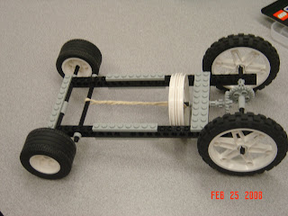 Picture: Rubberband Car "design"
The Results:
On the day of testing, we were given three trials where you would have a certain amount of time fixing, customizing and updating the rubber band powered car based on gathered analysis from each trial. Not only that, but this "prep" time enabled other groups to "gather" information from other designs around them, thus allowing for improvement with each passing trial. This could be called the test drives for the products and their inventors. But with each trial, it seemed that everyone was improving.
The first trial was very successful, yielding the farthest distance with the use of the rubber band. At this we took a gamble, adding more to the design. Essentially, this caused our car to travel a shorter distance while other cars began to gain in distance to it's "record" distance. And finally the last trial wielded the farthest distance out of all our trials, as well as the trials of the other groups. We proved our design to be successful, and in a real situation also "usable" in the eyes of the buyer when looking on to these test drives.
This project did not call for any sort of programming, but instead was one that "broke us in" to the concept of lego construction and design. A learning experience it was, and a successful project it had been.
Build a rubber-band powered vehicle to travel the furthest possible distance.
Our Solution:
We developed a car where the rubber band was fixed at one end and then straddled a spinning gear at the other end where by reversing the car the rubber band would wind around itself building potential energy. The strength of this design lied in its capacity to store potential energy in the rubber band in a fashion that did not compromise the integrity of the rubber band.
 Picture: Rubberband Car "design"
On the day of testing, we were given three trials where you would have a certain amount of time fixing, customizing and updating the rubber band powered car based on gathered analysis from each trial. Not only that, but this "prep" time enabled other groups to "gather" information from other designs around them, thus allowing for improvement with each passing trial. This could be called the test drives for the products and their inventors. But with each trial, it seemed that everyone was improving.
The first trial was very successful, yielding the farthest distance with the use of the rubber band. At this we took a gamble, adding more to the design. Essentially, this caused our car to travel a shorter distance while other cars began to gain in distance to it's "record" distance. And finally the last trial wielded the farthest distance out of all our trials, as well as the trials of the other groups. We proved our design to be successful, and in a real situation also "usable" in the eyes of the buyer when looking on to these test drives.
This project did not call for any sort of programming, but instead was one that "broke us in" to the concept of lego construction and design. A learning experience it was, and a successful project it had been.
Subscribe to:
Posts (Atom)